Introduction
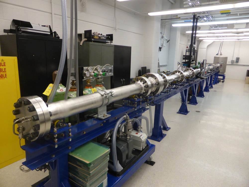
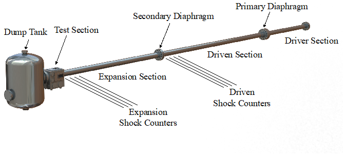
The Gas Dynamics Imaging (GDI) Laboratory is home to the Michigan Hypersonic Expansion Tube Facility (MHExT). The impulse facility is capable of generating aerothermal flow conditions representative of flight Mach numbers ranging between 4 to 11 with total enthalpies of up to 10 MJ/kg. It was designed to achieve maximum test times for conditions representative of Mach 6 to 8 flight to primarily study supersonic combustion phenomena. The facility has a modular design allowing for test time optimization over the full range of operating conditions. The expansion tube is 14 m long and has a honed and polished internal diameter of 14.4 cm.
Operation
An expansion tube, similar to other impulse facilities, is capable of generating high-enthalpy and Mach number flows representative of conditions found in supersonic combustors and re-entry vehicles. An expansion tube is comprised of three main parts referred to as the driver, driven, and expansion sections. Before each test run, the sections are separated by diaphragms and filled with gases to predetermined pressures. The driver is the high-pressure section which is filled with a gas with a high sound speed, typically helium. The driven section is filled with a test gas mixture of interest at a low pressure, while the expansion section is typically filled with helium at an even lower pressure.
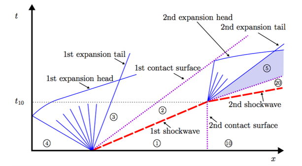
What differentiates an expansion tube from other impulse facilities is the process used to reach the final test gas aerothermodynamic state. Its operation can be thought of as two shock tubes being operated in series. The wave processes are illustrated in the space-time diagram below. A pair of waves (compression and expansion) is generated upon rupturing each of the two diaphragms. When the primary diaphragm is ruptured, a shock wave compresses the test gas and induces a bulk motion in the wave direction. The shock-processed test gas is then expanded through the unsteady expansion wave generated by the rupture of the secondary diaphragm. The unsteady expansion process further accelerates the test gas to higher Mach numbers as well as increases its total enthalpy. In essence, the operation of an expansion tube is similar to that of a shock tunnel except it replaces the steady expansion process across a nozzle with an unsteady expansion process.
Capabilities
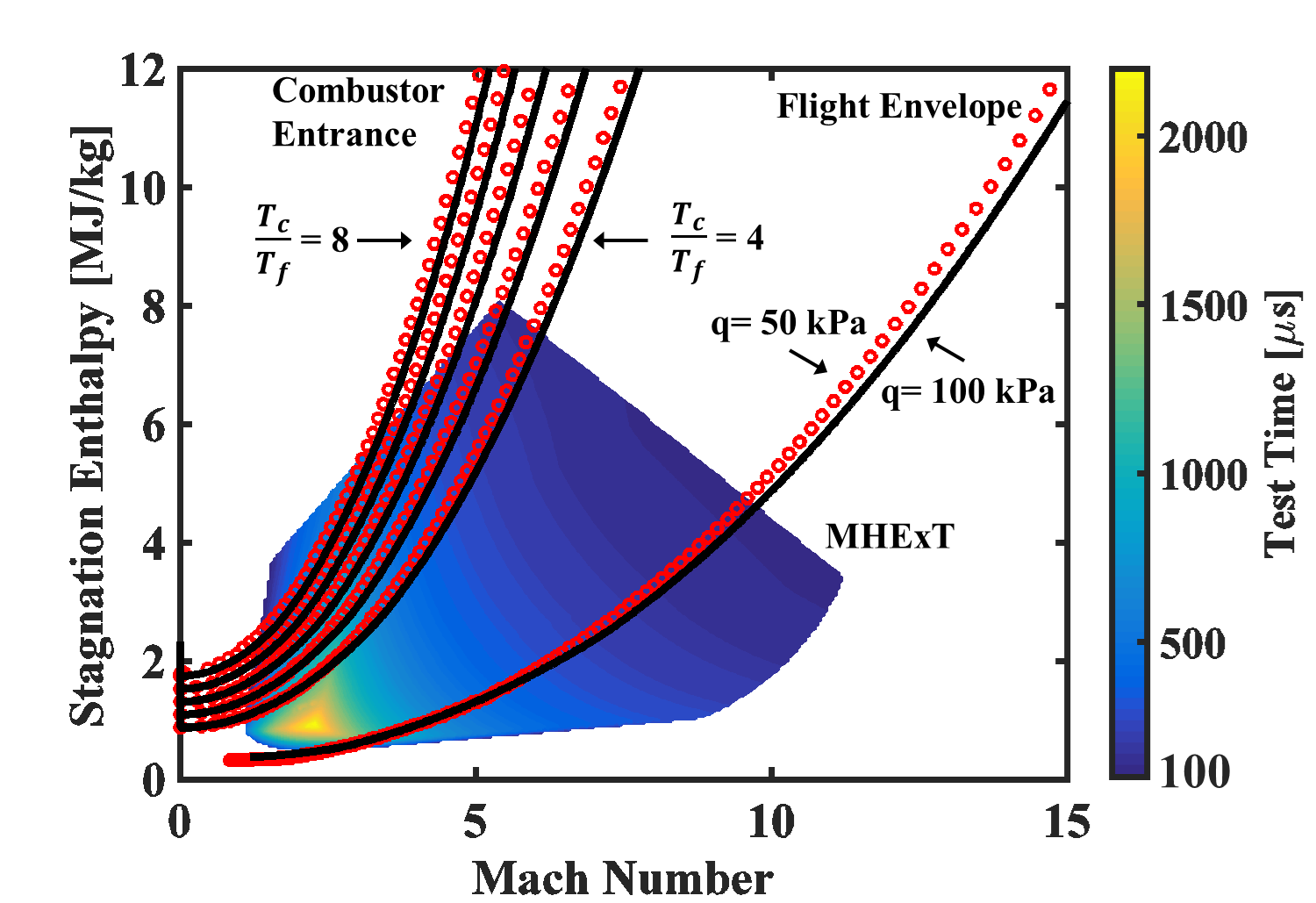
Our interests lie in studying supersonic mixing and combustion phenomena. The figure below illustrates the energy requirements to properly replicate conditions for supersonic flight. The curves on the right illustrate the flight Mach number and stagnation enthalpy for two flight envelopes with a fixed dynamic pressure of 50 kPa and 100 kPa. Following the inlet compression process, the combustor entry Mach number is reduced, while maintaining a constant stagnation enthalpy. Several curves are shown on the left, which pertain to varying levels of compression through the inlet.
Superimposed on this figure is a surface plot of the range of achievable test gas conditions with the MHExT facility. This surface plot indicates the achievable test times for varying flow Mach numbers and stagnation enthalpies. Because MHExT has a modular design, the current surface plot indicates the test times achievable with only one of its configurations, which is intended to maximize test times for conditions representative of flight Mach numbers ranging between 6 and 8.
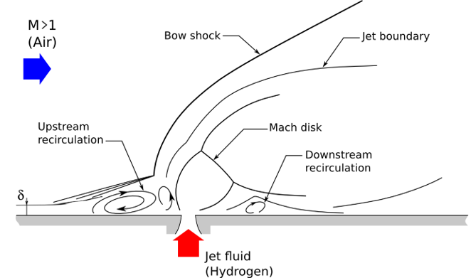
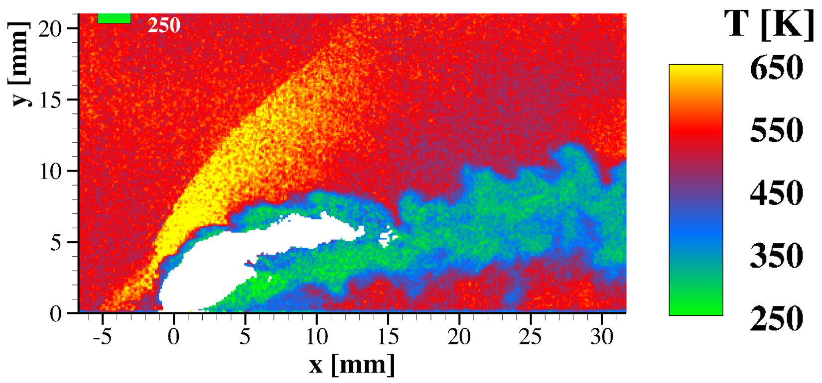
Additionally, PLIF and Schlieren images showing combustion/mixing of hydrogen injected into supersonic crossflow. Together, quantitative data can be extracted such as the temperature field.