
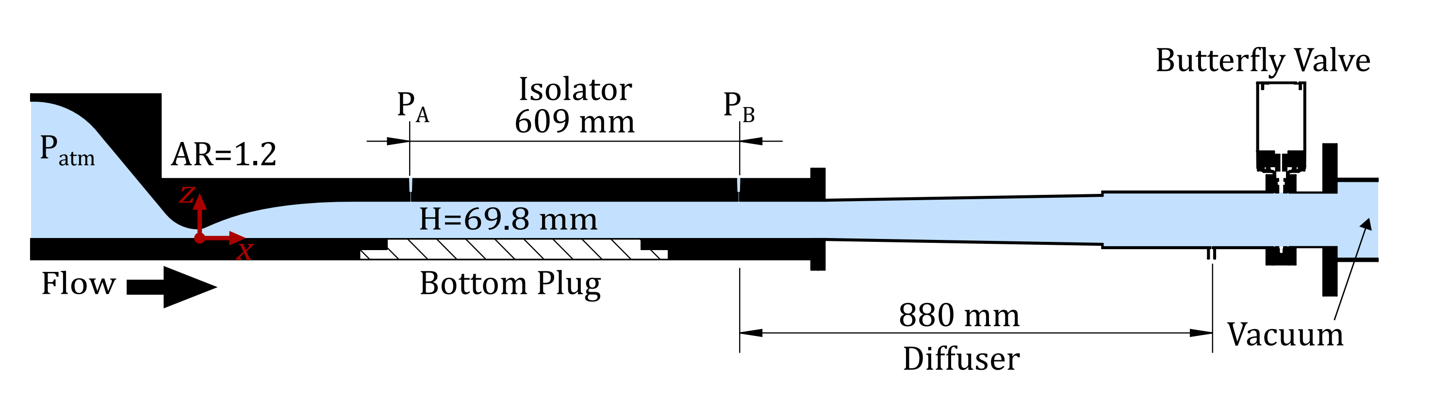
The Michigan glass wind tunnel is a vacuum driven facility that can be operated at Mach 2.0 or 2.75. The rectangular test section mimics several features of real high-speed inlets including three-dimensional shock-wave/boundary-layer interactions on the tunnel walls and separation in corners. Run times are up to 10 minutes. Glass sidewalls and bottom wall inserts provide optical access to a large portion of the tunnel. The top- and side-walls also have several static pressure ports.

Diagnostics
Schlieren | A folded Z type schlieren is used to image shock wave behavior throughout the tunnel. 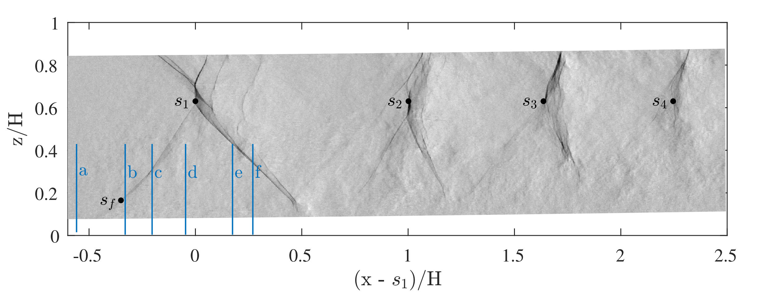 |
PIV |
The wind tunnel flow is seeded with micron-size synthetic oil droplets and then illuminated using two Nd:YAG lasers. The illuminated particles are imaged with two CCD cameras in stereo configuration relative to the laser sheet, thus providing all three velocity components. Velocity vectors are used to calculate other important flow properties including strain rate, vorticity, and turbulent fluctuations. |
Pressure |
Several pressure taps are distributed along the full length of the side-wall and along the bottom-wall |
Oil |
Oil flow visualizations have been used to determine time average flow topology along the tunnel walls. Variations in the oil patterns are indicators of separation zones and thus help determine the relative strength and spatial extent of interactions. |