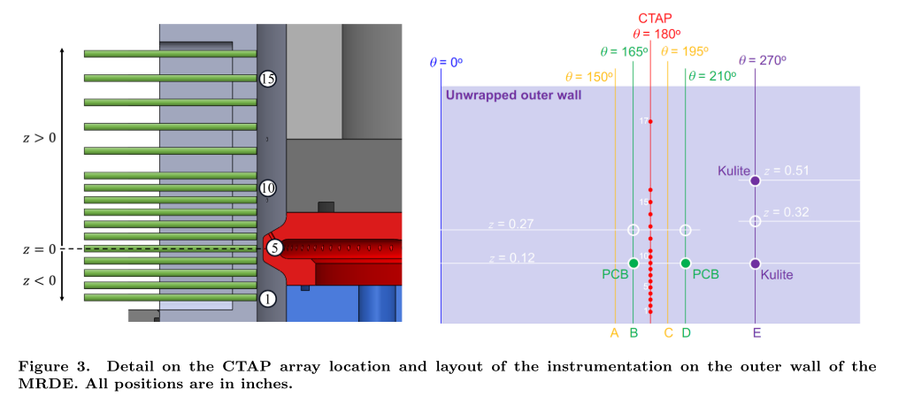
Our facilities are equipped to test various geometries of RDEs, such as a modular 6” RDE, an optically accessible RDE (racetrack) better suited for laser diagnostics, and an enhanced axial-air inlet (AAI) RDC with variable inlet area. In our enhanced axial-air inlet RDC, which is our most tested, we can operate at inlet area ratios (defined as the channel area to minimum inlet area) of 3, 4 and 5. Our AAI RDC is equipped with flush mounted high speed Kulites in the channel as well as in the air plenum. The RDC is also instrumented with 17 CTAPS running along the length of the channel. Additionally, through an optical access port PMT OH* chemiluminescence images can be obtained for pointwise measurements of heat release. The rear-view of the RDC recorded using high-speed imaging for determining the number of waves, there frequency and speed. Our RDC is also mounted on a thrust stand.
Five independently controlled fuel lines run to the RDE allowing for different mixtures of gaseous fuels to be studied. Mostly we operate with hydrogen-air mixtures. The system can currently push 1 kg/s of air as oxidizer, with capabilities to extend this to 2 kg/s. The air can be pre-heated up to 600 K and have possible oxygen enrichment. The flowrates of fuel and oxidizer can be varied mid-run to study transient effects. Nominal test conditions range from 0.5-0.4 kg/s of air and global equivalence ratios of 0.6 – 1.4. A more detailed description of each subsystem can be found below.
Facility
The system is composed of an air/fuel distribution manifold, fuel injector section, the detonation channel, and the exhaust system. The air and fuel are injected separately in order to control the equivalence ratio of the flow. The test facility utilizes a high-pressure air system and high temperature exhaust which can handle up to 0.5 kg/s of air. Electro-pneumatic solenoid ball valves and precision orifices are used to control and meter the supply of reactants to the RDC. Electronic pressure regulators are used in conjunction with air loaded regulators to set the fuel and air pressures. The pressure is measured on both sides of the orifices during operation to verify choking. The mass flow rate through the RDE is computed using the orifice upstream pressures for all flows and injectors except for the ONERA air stream, which hard-chokes between the inner plenum and detonation channel. Thus, in this case the pressure in the air plenum is used to set the air mass flow rate.
RDC
The AAI RDC has an outer detonation channel diameter of 154mm and inner channel diameter of 138.8mm, resulting in a channel gap width of 7.6mm. 60mm downstream of the fuel injectors is a sapphire window for optical access into the channel. The channel length can be varied using spacers from 104mm to 119mm. The RDC is mounted on a thrust stand and connected to an exhaust system. Ignition of the RDC is done via a radial piloted afterburner.
Injectors
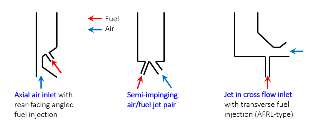
The RDC is modular and can house different air- and fuel-handling configurations: (a) axial air inlet (AAI); (b) radial air inlet (RAI); and (c) semi-impinging discrete jets (SIJ). Fuel is injected from the rear-facing portion of the contour through 120 discrete evenly spaced injection portholes of diameter 0.89mm arranged around the circumference of the contour.
Instrumentation
The outer wall of the detonation channel is instrumented with 17 CTAPs to measure the axial variation of average pressure along the length of the channel. The taps are 36 inch long, 1/16 inch diameter tubes which attach to each port with a pressure transducer at the far end. The high-speed pressure sensors installed included a Kulite XTEL-190L-250A pressure transducer in the air plenum and a flush mounted water-cooled Kulite EWCTV-312-500A pressure transducer near the base of the detonation channel. All low speed static pressures are recorded at 200 Hz, while high speed pressure data is collected at 500 kHz.
Afterburner
The testing sequence of this RDC is different from many other RDC setups, in that the ignition source of the RDC is a premixed radial afterburner (pilot) located downstream of the detonation channel rather than a conventional pre-detonator The afterburner causes ignition of the mixture, generated within the detonation channel, as it leaves the system which causes the flame to travel upstream into the detonation channel until it anchors itself above the injector.
Window
Optical access into the detonation channel is achieved through the use of sapphire windows. The outer body sapphire window has a 25 mm diameter, and the inner body sapphire window has a 12.5 mm diameter. These windows are centered about 60 mm downstream from the fuel injectors, which corresponds to where the detonation wave is believed to exist.
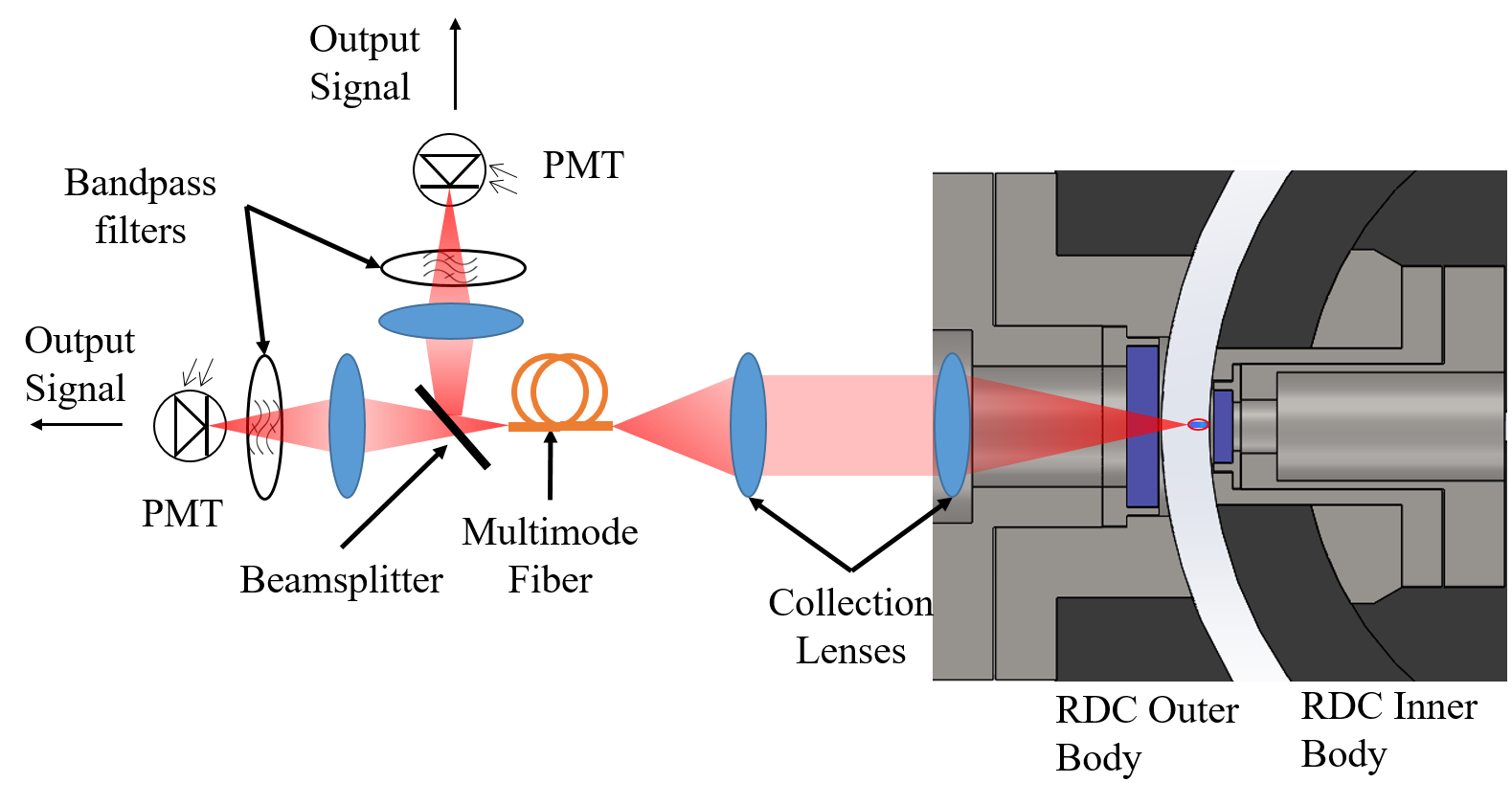
OH* Chemiluminescence
The optical train used for the OH emission experiment was designed to interface directly with the hardware with the outer window mount. Lenses were used to collect emission light onto a multimode fiber bundle that coupled light directly onto a photo multiplier tube (PMT) equipped with suitable bandpass optical filters to reject unwanted light and collect light over an intended spectral region. The optics were chosen such that the area of the multimode fiber was the sampling area of the focal points within the detonation channel, making the measurements approximately point measurements in a region in the middle of the detonation channel. From these point measurements, qualitative and quantitative information on the spatio-temporal evolution of the detonation wave and heat release distribution can be inferred.
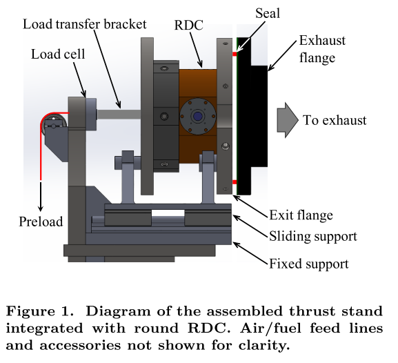
Thrust
The combustor is mounted on a frame that sits and translates freely on a rail system. The point of deflection on the arrangement is colinear to the axis of the combustor and it is centered on the load cell axis. The range of the load cell is 1000 N and can measure both tension and compression forces. The output of the load cell was recorded at 200 Hz by the existing data acquisition system While the load cell will output the gross thrust of the engine, the base pressure forces at the exit plane need to be accounted for to find the net thrust produced by the combustor.
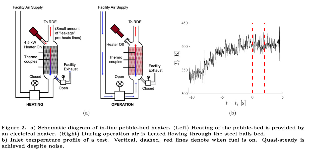
Pebble Bed
An electrically heated in-line pebble-bed system has been developed and integrated into the RDC system to provide heated air to the RDC. The system was designed to heat the incoming air up to 800 K and sized to support a 15 second test for air mass flows of up to 1 kg/s. The pebble bed has thus far been tested up to a mean temperature of 600 K, although the achieved maximum temperature entering the RDC is 500 K for a non-reacting condition and 480 K for a reacting condition.